Basic BringUp
This chapter guides you through the basic bring-up of the control pilot (CP), proximity pilot (PP), and relays for both AC and DC chargers. It is a prerequisite to the more specific bring-up guides for AC and DC charging.
Control Pilot
The first step - both for AC and DC - is to verify the control pilot (CP) signal functionality and stability. A lot of problems we have seen in the field are related to unstable CP signals. So, this step is key for a stable product.
The normative requirements are described in IEC 61815-1. This section will guide you through the most important requirements specified in the norm to be tested at bring-up. It is not complete, IEC gives more requirements that should be followed at design time.
Warning
For all parameters: Ensure that the limits are guaranteed over the complete temperature and input voltage ranges as well as all other environmental factors over the complete lifetime of the product.
Being on the edge of the range during bring-up already, will most likely result in out-of-spec performance in production due to part tolerance, component aging etc.
First, verify PWM output with no car / nothing connected to it.
You should have an EVSE board support driver for your hardware already.
In this how-to-guide, we will use the BringUp & Qualification tool from EVerest to select the different CP states manually. This ensures that (a) the CP signal is correct and (b) the wiring up to the EVerest HW driver is also correct.
You can find an example configuration file in EVerest for the BelayBox that you can modify to use the correct BSP driver for your hardware:
config/bringup/config-bringup-yetidriver.yaml
Before you start the bring-up, make sure there is no other EVerest instance running (e.g. do a systemctl stop everest).
On the target, start it the following way:
/etc/everest/run_tmux_helper.sh /etc/everest/bringup/config-bringup-yetidriver.yaml /usr
Now, connect an EV simulator where you can set the states A/B/C/E and simulate a diode failure / loss of PE connection between EV and EVSE failure.
State D is not really used anymore nowadays; it dates back to the times when lead-acid batteries were used that leak hydrogen gas during charging.
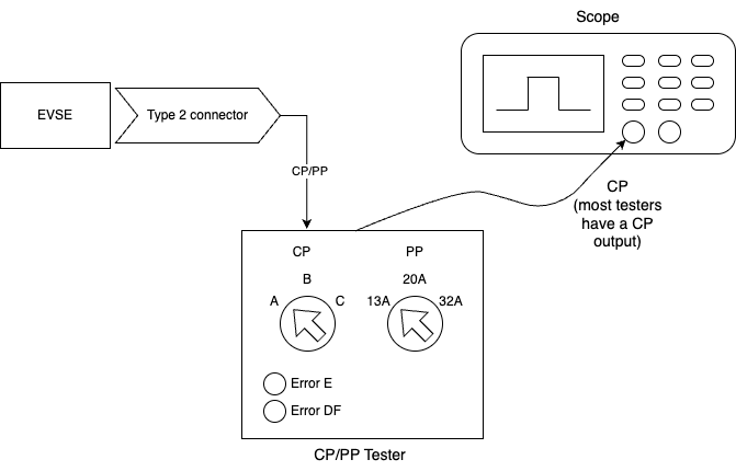
Connect your EVSE, the simulator and a scope similar to this:
Now go through the following checklist step by step:
Tip
Select PWM off / X1, switch EV simulator to state A. This should output constant +12 V on the CP line.
☐ Select AC coupling on the scope and verify the ripple noise. There is no hard limit, but we recommend keeping it below 100 mV VPP.

☐ Switch to DC coupling, measure DC voltage range. It must be +12 V +/- 5% (11.4 V to 12.6 V). Use a multimeter if your scope does not provide sufficient DC accuracy.
Now select PWM State F. This outputs constant -12 V on the CP line.
☐ Select AC coupling on the scope and verify the ripple noise. There is no hard limit, but we recommend keeping it below 100 mV.
☐ Switch back to DC coupling, measure DC voltage range. It must be -12 V +/- 5% (-12.6 V to -11.4 V). Use a multimeter if your scope does not provide sufficient DC accuracy.
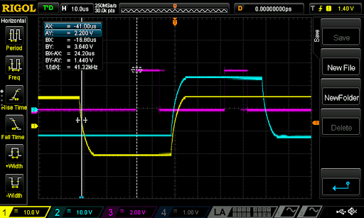
Select PWM on with a duty cycle of 5%, and connect the EV on the simulator (State B). Note that the images below were done in state A, but you should use state B.
☐ PWM frequency: Must be in the range 980 Hz - 1020 Hz. It should be 1000 Hz.

☐ Measure the (high) pulse length for the 5% duty cycle. Measure the time between the zero crossings. It should be 50 µs.

☐ Equivalent source resistance: 970 - 1030 Ohm. Using a 1% 1-kOhm resistor should be sufficient to fulfill this requirement if the output of the PWM generator is low impedance.
☐ Set state B and verify that the PWM duty cycle can be set to any value between 5% (HLC) and the maximum current value your EVSE supports (e.g. 53.3% for 32 A for AC). For AC, the maximum PWM for your application can be calculated with:
\[dutycyclePercent = maxAmpere / (0.6 * 100)\]For DC, it is always 5%. The range from 5% to 10% is not used and it is ok to not support PWM in that range.
☐ Set state B, which will have a PWM voltage range from +9 V to -12 V. Verify rise time is below 10 µs from 10% (-9.9 V) to 90% (6.9 V) of the signal. The example has a rise time of 4.3 µs.

☐ State B: Verify fall time is less than 13 µs. As you can see in the screenshot, the fall time is 10.68 µs, which is longer than the open circuit time due to the diode in the EV simulator.

☐ Set state C. Verify rise time is below 7 µs from 10% (-10.2 V) to 90% (4.2 V) of the signal. The example has a rise time of 3.08 µs.

☐ State C: Fall time must be less than 13 µs from 90% (4.2 V) to 10% (-10.2 V) of the signal. The example has a fall time of 12 µs which is in range.

☐ Set State E (sometimes called CP Error or so). The CP signal should be at 0 V constantly according to the norm. Some EV simulators only short after the diode as seen in the screenshot. Make sure that your CP detection circuitry also treats that as state E.

☐ Test diode failure detection: Short the diode on the EV side. Many off-the-shelf EV simulators can be easily modified with an extra push button if it is not included already. Verify that the BSP throws an error (DiodeFault)
☐ Test short state changes: Toggle between states B, C, B quickly to produce a short time in state C (about 200 ms or less). The short state C should be reliably reported to EVerest. It is a common issue that the safety MCU filters out state durations that are too short. This will cause issues with the BCB toggle wakeup sequence detection of ISO 15118-3.
☐ Disconnect PE between EV and EVSE. This should be detected as an error or state A.
Now that the basic functionality is working, test stability of the state detection. Most cheap EV simulators only use the nominal resistor values to test the states, but ideally you have a simulator that can use the minimum and maximum values for each state.
Ensure that the following states are detected correctly over the complete range:
State |
Minimum R applied by EV |
Nominal R |
Maximum R applied by EV |
|---|---|---|---|
B |
1870 Ω |
2740 Ω |
4610 Ω |
C |
909 Ω |
1300 Ω |
1723 Ω |
If possible, use a debug GPIO, that shows the exact timing of the ADC sampling and connect it to the second channel of your scope like this:
In the screenshot, two PWM signals are shown. The cyan one is 5% duty cycle and the yellow one is 95% duty cycle. The magenta signal shows the time the ADC reads the signal. As you can see, the first magenta pulse is nicely aligned with the end of the low part of the PWM, so it will read the -12 V reliably even at 95% duty cycle.
The second magenta pulse is nicely aligned with the high part of the PWM providing stable readings even at just 5% PWM. The 5% case is the more critical one, as very high duty cycles are not typically used.
The most common problem for unstable CP detection (which results in charging sessions breaking and potentially leads to relays opening under full load) is that the ADC sampling time starts too early or ends too late. In both cases it will capture part of the edge of the high part of the signal, resulting in a lower measured value. This can lead to e.g. a state C detection while it is state B in reality.
Make sure to observe the correct timing under real conditions with a car attached. With an open circuit and the 2 µs rise time, timing may be perfect, but with a car attached and a 10 µs rise time it may not work correctly.
This is especially critical at the 5% duty cycle as the high part is only 50 µs long. Never sample in the first 10 µs. When using the MCU to synchronize ADC and PWM, make sure that interrupt priorities are set correctly so that additional (interrupt) load on the MCU does not lead to delayed ADC triggers sometimes.
This needs to be 100% stable over long periods of time (hours/days !). Some MCU (especially those made for motor control) can trigger the ADC synchronously with the PWM generation without involving an interrupt routine.
Apply some filtering and averaging in software (e.g. average over 10 pulses, filter out the highest and the lowest value or similar). It should not detect a wrong state, not even a single time.
Do not filter too much though. This is another common flaw that should be tested at this stage: IEC 61851-1 requires switching off power when the EV transitions from C2 to B2 within 100 ms. As the relays also take some time to open, do not delay the detection of the state change by more than 50 ms due to filtering. Report all state changes to EVerest, also those that are short-lived. Otherwise, some features will not work correctly, e.g. ISO 15118 resume after pause.
Now test with several different real cars as well, as the implementation on the EV side differs a bit across vendors and models.
Relays
The AC output contactor bring-up is the same as for the DC output relay.
Verify the correct function of the relay. Command the MCU to close the relay (use the BringUp tool’s Allow power on button) and verify it closes the relay in a timely manner (given that there is no RCD error etc).
EVerest will issue the allow_power_on/force_power_off commands to the BSP driver just like you can do it in the BringUp module. It is important to understand the logic:
If the safety MCU receives an “Allow power on”, it may switch on the relay if all other requirements are met (e.g. CP in state C, RCD current ok, temperature in range etc). The MCU may decide to not switch on the relay if some other local requirements are not met. It is just important to always report the actual relay state with the PowerOn/PowerOff events.
The following checklist tests if the safety MCU behaves correctly in regard to the CP state C2. It does not test for other requirements such as over-temperature etc.
If the safety MCU receives a force power off from EVerest, it shall open the relay immediately.
Complete the following checklist:
- ☐ State A, PWM off, force power off. Set State B then enable PWM 5% and then C.Then allow power on. Relays should switch on within a short period of time after sending allow power on. You should see a “Power On” event (the time between “Allow power on” and the “Power On” feedback event should be short, e.g. less than 300 ms or so, no hard limit here). Click on “Force power off”. You should see a “Power Off” (same timings as above). These timings should be short - see below. You can click “Power On/Off” a couple of times and verify the timing of the feedback.
☐ Toggle the relay on and off a couple of times and observe the PowerOn/PowerOff events. There should be exactly one event for each on or off switching of the relay. Make sure that there are not multiple PowerOn/PowerOff/PowerOn events being generated because the relay is bouncing.
☐ State A, PWM off, state State B. Then enable PWM 5%, allow power on. Relay should not close. Wait a few seconds, then set state C. Relay should close immediately after entering state C. Ignore the time shown on the “Power On” event. It measures the time from the last “Allow power on” command to feedback.
☐ State C, PWM 5%, Relay closed. Then set state B. Relay should open immediately (max 100 ms). Go back to state C. Relay should close again. (IEC 61851-1:2017 Table A.6: Sequence 8.1)
☐ State C, PWM 5%, Relay closed. Then stop PWM but stay in state C. Relay should open after a minimum of 6 seconds. (IEC 61851-1:2017 Table A.6: Sequence 10.2)
Timing on closing relays is quite relaxed, but ISO 15118 has a limit of one second from the ISO command to switch on to the ISO feedback that it was done. As most of the time is spent in the ISO communication stacks, the MCU should ensure that the time from commanding the relays to close to receiving the feedback that it was closed correctly should be in the order of 100 ms in the MCU.
Timing on opening the relays is more critical and a good value is opening within 50 ms after the command arrives at the latest. IEC 61851-1 requires the relay to be open after a maximum of 100 ms after state C->B (or A etc) transition.
Verify that the feedback is reported correctly. A typical error during bring-up with EVerest is missing relay feedback. Make sure they are always reported to represent the relay state correctly. Send the events on any change, regardless of the cause of switch on or off in the MCU.
Proximity Pilot
This section is for Type 2 CCS Chargers. PP works a little different for Type 1 Chargers.
For AC chargers with a type 2 socket, PP needs to be verified as well. AC Chargers with a permanently attached cable do not use the PP signal. DC chargers normally do not use PP as they have an attached cable, however it may be used in some configurations to e.g. detect a cut cable.
Most of the EV simulators can only switch the nominal resistor values for 13 A/20 A/32 A. To test the PP functionality, you could e.g. use small wired resistors and connect them manually between PP and PE or build yourself a small tester that can do the minimum/nominal and maximum resistor values.
Verify that the BSP reports the correct cable ampacity for all values in this table:
Cable ampacity |
Minimal R |
Nominal R |
Maximal R |
|---|---|---|---|
13 A |
1100 Ω |
1500 Ω |
2460 Ω |
20 A |
400 Ω |
680 Ω |
936 Ω |
32 A |
164 Ω |
220 Ω |
308 Ω |
63 A 3ph/70 A 1ph |
80 Ω |
100 Ω |
140 Ω |
Values below 60 Ω above 4500 Ω should be treated as errors and the BSP should report “None” as PP ampacity. Resistor values in between the defined ranges in the table should be treated as the lower ampacity value.
Ensure that PP is measured quickly after plug-in of the vehicle. The MCU should also monitor PP throughout the complete charging session and report an error if PP connection breaks.
With CP/PP and relays, the minimal setup for AC charging has already been verified.
Tip
In addition, you may want to verify a few more components before charging a real car. But you can also do this later on.
Once the CP signaling has been verified you can continue with the bring up of the powermeter and the bringup for AC or DC, depending on your use case.
Authors: Cornelius Claussen