Hardware Architecture
This page gives some ideas and guidance on the general architecture of AC or DC charging stations and helps to choose the best components.
DC architecture
The following block diagram shows a typical architecture for a DC charger:
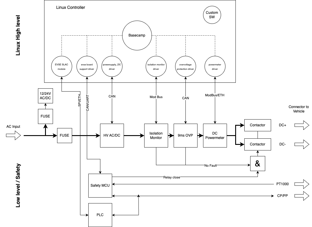
On the top, the Linux high-level controller runs EVerest plus all customer specific software. EVerest connects to the hardware components through the EVerest-integrated hardware drivers or external custom drivers that use the EVerest APIs to communicate with EVerest.
The hardware components are typically connected to the Linux controller by CAN, RS458, Ethernet or similar. They may be different in your design.
On the bottom, a typical low-level controller design is shown. Handling the electrical safety in the low-level design is crucial, as the high-level Linux controller cannot guarantee timings or even that it is running at all.
The safety MCU shall handle at least the following functionality:
Control pilot signal I/O: It outputs the PWM according to the duty cycle controlled by EVerest and reads states A-F back.
Contactor close signal: It receives an “on/off” flag from EVerest and also internally creates a second “on/off” flag. As an example, the internal flag is only “on” if e.g. CP is in state C and no overtemperature is detected with the PT1000 on the connector pins. It outputs a contactor close signal only if both flags are “on”. It is responsible for opening the output contactors in case of CP state not C, over-temperature errors, loss of PE connection and all other critical faults - independent from the Linux high-level control.
The isolation monitor and the over-voltage protection circuitry shall also be able to directly open the output contactors, independent of other components. This fault signal may also be routed through the safety MCU. EVerest will read values from the isolation monitor and the OVP module as well and will issue a shutdown, but this will come (1) too late and (2) the safety shutdowns shall be working even if Linux is down.
The safety MCU may require certification for e.g. UL as it contains safety in software functionality.
The output contactors should be the last component before the plug to the EV. Then they fully disconnect the user from all internal circuitry, so as long as the contactors are open, no internal fault causes a safety hazard on the output plug pins.
The block diagram above shows only two output contactors to fully switch the output on and off. Some power supplies may require a third contactor that switches a precharge resistor in the output path. This is required if the DC power supply does not have an accurate and fast current limit functionality at very low limits (e.g. 1A).
If the DC power supply cannot ramp down the voltage quickly, an additional contactor may be required that switches a load resistor on the output for active discharge.
Both are not shown here as they are typically not required with most EV charging power supplies.
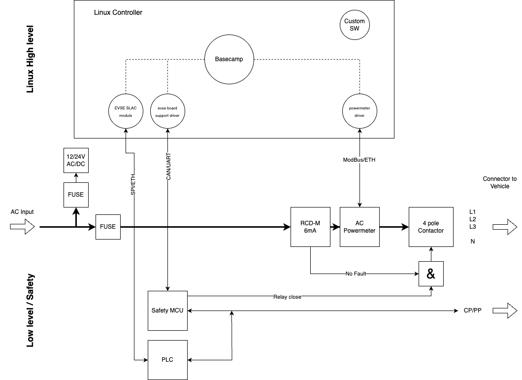
AC architecture
The typical architecture for an AC charger is similar to that of a DC charger, but has fewer components on the power path. The requirements for the safety MCU apply here as well.
Choosing components (AC)
Output contactors
The output contactors shall have a mirror feedback contact. With many DIN rail components, the mirror contact (or auxiliary contact) can be mounted as a snap on device. Ensure that the minimum current requirements are met. Some contactors require between 10 mA and 50 mA of current flowing through the mirror contact to ensure the contacts remain clean.
Especially for PCB mount contactors, check the contact air gap. It should be at least 3 mm (check IEC 61851-1:2017 8.1 for alternatives). The 3 mm found in the IEC 61851-1 originates from IEC 60664-1 Table F.2 for 4 kV rated impulse voltage, overvoltage category 3, inhomogeneous field. For a homogeneous field, 1.2 mm would be enough.
In general, a 4-pole contactor should be used. Some applications (such as solar-based charging) may want to use two 2-pole contactors to allow for 1 ph/3 ph switching. See the chapter on RCD below on limitations when using this configuration.
A significant part of the generated heat comes from the coil current. It is recommended to lower the coil voltage as per specifications from the manufacturer after the switching.
Examples for PCB mount 4-pole relays: Panasonic AHER4191, Omron G9KC.
RCD
Integration of an RCD is optional; but if it is not in the charging station it has to be installed in the upstream installation outside of the charging station. RCDs shall comply with one of the following standards: IEC 61008-1, IEC 61009-1, IEC 60947-2 and IEC 62423.
For AC charging, a type B RCD is generally required to protect against both AC and DC fault currents.
The RCD Type B may also be integrated into the charging station, simplifying the installation requirements.
As Type B RCDs are quite expensive, a common solution is to integrate a Type A RCD for AC faults and a DC fault current detector as a separate module.
In this case, the 6 mA DC fault detection module should follow IEC 62955 (check IEC 61851-1:2017 8.5; the standard says the IEC 62955 is an example to be compliant).
Such modules are available as PCB mount or as individual modules, e.g. from Bender/Vacuumschmelze (Benvac), Würth Elektronik, Western automation and several others.
Note
The fault output of these modules shall directly open the output contactor without waiting for Linux and EVerest. EVerest should be informed after the switching off so that the error can be reported.
If the general output contactor is used for RCD switch off, IEC 62955 requires a 4-pole relay. E.g., two 2-pole relays are no longer allowed by this standard. In this configuration a combination of two 2-pole contactors for 1 ph/3 ph switching followed by a 4-pole relay for RCD switch off may be required.
Power meter
For AC applications, a lot of different DIN rail components are available from many different manufacturers. Typically, they have a ModBus RS-485 interface to the host. Most of them can be easily added to EVerest by simple register mapping in the GenericPowerMeter module if not supported already.
Make sure they are MID-compliant for CE.
If German Eichrecht is required, it is a bit harder to find power meters. They are available from Bauer or EMH, for example.
Choosing components (DC)
Isolation monitor
Most isolation monitoring devices come as DIN rail devices. Check the following specifications:
Certified to IEC 61557-8 or equivalent (see IEC 61851-23: 2023 CC 4.1.5)
Measures the isolation resistance (total to PE or individually for negative to PE and positive to PE). Measurement range should include 100 kOhm with some margin, e.g. 50 kOhm - 500 kOhm.
Voltage range >= maximum voltage of DC power supply
Communication interface with host system (e.g. ModBus RS485, CAN, …)
Self-test functionality via communication interface (trigger start of self test, read result). Relying on automatic periodic self-testing is no longer allowed in the 2023 edition of IEC 61851-23.
Self-test should be quick (e.g. < 10 s), long self-tests may lead to timeout issues with certain vehicles
Time needed to detect a fault should be short (e.g. <5s)
Measures the voltage between DC positive and negative wire and report via communication interface
Separate fault output that can be used to trigger an emergency shutdown independently from the charge controller (and EVerest!)
Ideally: Over-voltage detection and shutdown according to IEC 61851-23: 2023 6.3.1.106 (we are not aware of a product that has this at the time of writing)
Note
We are not aware of a product that fulfills all of these specifications, so some trade-offs may need to be made and additional hardware may be required. Example devices are Bender isoCHA425, Dold RN 5897/021 or Acrel AIM-D100.
Over voltage monitor
IEC61851-23:2023 has stricter requirements than the earlier version. One of the new safety requirements is a fast over-voltage protection, that triggers if the DC voltage is above the limits specified in the standard for 9 ms.
The actual detection and shutdown needs to be handled outside of EVerest (e.g. in dedicated hardware). EVerest can only provide the value of the over-voltage limit (as it depends on the maximum voltage reported by the EV) and start/stop the monitoring.
Refer to IEC61851-23:2023 6.3.1.106.2 for requirements.
Note
We are not aware of an off-the-shelf product that fits this requirement.
AC/DC converter / DC power supply
For new products we highly recommend to have a voltage range of 150 V to 1000 V for best compatibility for CCS. Charin suggests 920 V as the high limit, which may be on the edge already with e.g. Lucid Air. The lower limit is a bit flexible, but we recommend not to have more than 200 V.
Some vehicles refuse to charge if the lower limit is too high, even if they do not require such a low voltage.
Another important topic is the current capability. Some power supplies have quite low current limits, e.g. 30 A for a 30 kW power supply. This means it can only reach 30 kW on a 1000 V vehicle, while it will be limited to 9 kW on a 300 V vehicle.
Many power supplies actually have two 500 V converters internally, and they can be arranged in a serial or parallel configuration. In this case, it is often possible to get a higher current output for the low voltage vehicles in parallel mode. The driver code should use this functionality and switch automatically between the two modes.
High quality power supplies often have a constant power output, e.g. they can deliver the full 30 kW over the full voltage range. Those will give the best user experience.
Other important features are full protection (fully protected against shorts / load dump under full load), noise, efficiency and reliability.
Example devices are UUGreenPower, Huawei, SCU, Tonhe or Infypower.
Output contactors
Output contactors shall have the capability to open the contact at the maximum current possible in the system. Most contactors survive this only a limited number of times, e.g. three times before they need to be replaced.
We recommend that the low-level safety architecture ensures that the DC power supplies ramp down shortly before the contactors open in an emergency shutdown to protect the contactors. If this is not possible, the recommendation is to use contactors that are robust enough to withstand this quite often.
Under normal conditions the contactors always switch at zero current, but due to the poor quality of EV side implementations emergency shutdowns under full load will happen.
The contactors shall also have mirror feedback contacts so that EVerest knows when they are fully open/closed and stuck contactors can be detected. Ensure that the minimum current requirements are met. Most contactors require between 10 mA and 50 mA of current flowing through the mirror contact to ensure the contacts remain clean.
Verify that the contact gap is in accordance with IEC 60664-1 for the maximum voltage.
Power meter
For DC applications, different DIN rail components are available from many different manufacturers. Typically, they have a ModBus RS-485 interface to the host.
Make sure they are MID-compliant for CE.
If German Eichrecht is required, it is a bit harder to find power meters. They are available from LEM, DZG, AST, Isabellenhütte or Carlo Gavazzi, for example.
Authors: Cornelius Claussen